 option from the Navigation pane.
Connect Groups and Devices define how RCS Connect instances are organized and how they interact with the devices (Source Devices and Destinations) assigned to them within the Workflows panel. RCS Connect typically operates within an organization’s private network, allowing it to communicate directly with internal devices and endpoints. Messages from RCS Cloud are delivered to these devices using the correct protocol and destination address through a secure channel maintained by RCS Connect.
A Connect Group manages one or more devices. This allows flexible configuration—for example, one group may contain 20 devices dedicated to HD Radio metadata delivery, while another group may contain a single device responsible for file‑writing, which generates files based on AudioDisplay metadata output. A third group might monitor a file path and upload discovered files to an RCS Cloud service for processing.
Each Connect Group can include multiple RCS Connect instances. When more than one instance is present, failover is automatic: if the active instance becomes unavailable, another instance in the group immediately takes over. Groups with only one instance do not provide failover. All instances within a group are identical and manage the same set of devices, although only one instance is active at any given time.
If load balancing is required, multiple Connect Groups should be created, with devices distributed across the groups. Devices cannot be automatically moved between groups, but any changes made in the user interface are applied immediately to both active and standby RCS Connect instances.
Click for help links for this topicClick for help links for this topic
Connect Groups and Devices list
Create new Connect Group/+New Group button
Working in the Connect Groups and Devices panel
Create a Connect Group and add Devices
Select the Connect Groups and Devices option from the Navigation pane.
Click any area for help.
Click any area for help.
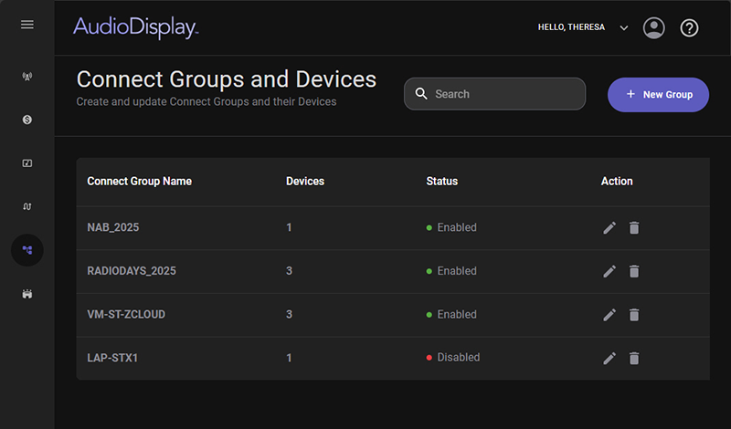
The Search field, located at the top of the Connect Groups and Devices panel, functions as a dynamic, real‑time search tool. As the user types, the system instantly filters and updates the Connect Groups and Devices list, allowing them to quickly locate specific groups without needing to scroll or navigate manually. This live‑search behavior ensures faster access to items and supports efficient navigation within large collections.
The list in the Connect Groups and Devices panel lists all the Connect Groups for the organization. The following details are shown in this list for each Connect Group.
Connect Group Name - This is the Group name given to the Connect Group when it is created.
Devices - The Devices column shows the number of devices in the Connect Group.
Status - Indicates whether the Connect Group is currently enabled or disabled. To change the status, select the Connect Group from the list to open the Edit Connect Group panel. Then, use the Enable toggle button to enable or disable the group.
Actions - The Actions column provides quick options to manage Connect Groups:
 Edit – Opens the selected Connect Group for editing.
 Delete – Prompts for confirmation before removing the Connect Group. Select Yes to continue or No to cancel.
To create a new connect group click the + New Group button in the top-left corner of the Connect Groups and Devices page.
Click any area for help.
Click any area for help.
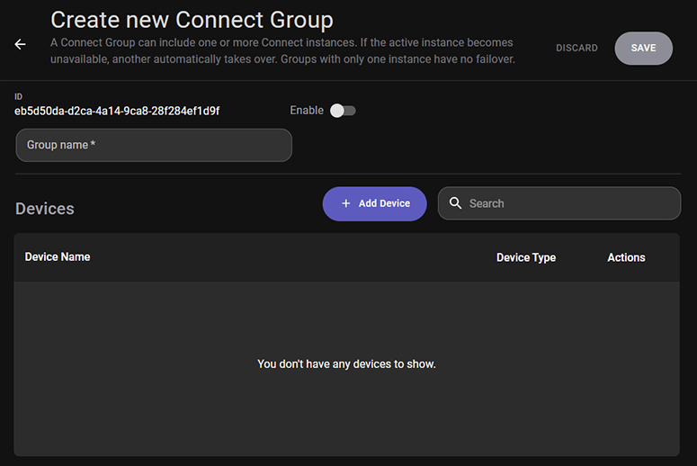
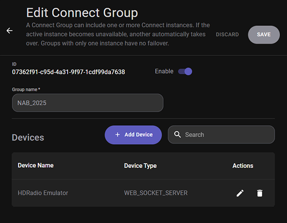
The ID is a unique identifier assigned to the device when it is created. This ID is read only.
The Enable toggle allows the user to enable or disable the Connect Group as needed. This is disabled by default when the Connect Group is created.
The Group name is a required field for the Connect Group. This name is used to easily identify the group in the Properties panel of the Source Device and Destination nodes in the Workflow canvas.
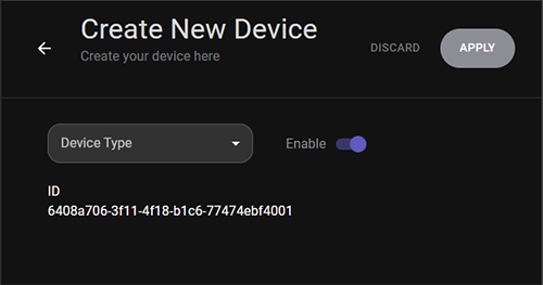
The +Add Device button opens the Create New Device panel, where you can configure new devices for use within AudioDisplay. Each device is automatically assigned a unique ID.
Selecting a Device Type reveals the configuration fields required for that device. Fields marked with an asterisk (*) are required.
Below are detailed descriptions of each supported Device Type and its configuration fields.
Device Types: Click for help linksDevice Types: Click for help links
Each device has the following common fields:
Enable – Turns the device on or off. This allows the device to be disabled without removing it from the connect group.
Name – A user‑defined label for identifying the device in the system.
A TCP Ping device tests the reach-ability and performance of a remote host. It sends ICMP echo requests and measures the response time, packet loss, and overall connection quality. This is useful for diagnosing network latency, connectivity issues, or intermittent failures.
The following configuration fields are displayed when TCP Ping is selected as the Device Type:
Timeout – The maximum time (in milliseconds) the device will wait for a ping response before marking it as failed. Higher values tolerate slower networks; lower values detect latency issues faster.
IPv4 / Hostname – The target host to ping. Accepts:
IPv4 address (e.g., 192.168.1.10)
Hostname (e.g., server.local)
A TCP Sender initiates a TCP connection and sends data to a receiving device. It is commonly used for transmitting messages, commands, or continuous data streams.
The following configuration fields are displayed when TCP Sender is selected as the Device Type:
IPv4 / Hostname - The destination server or device to which TCP data will be sent. Accepts:
IPv4 address (e.g., 192.168.1.10)
Hostname (e.g., server.local)
Port - The TCP port number on the remote host that will receive the data. Must match the listening port of the receiving device.
A TCP Listener waits for incoming TCP connections on a specified port. Once connected, it receives messages from TCP clients and can trigger actions based on the received data.
The following additional configuration fields are displayed when TCP Listener is selected as the Device Type:
Port - The port on which the device listens for incoming TCP connections. Only one device can listen on a given port at a time.
A TCP Client initiates a connection to a TCP server or another client device. It sends data and waits for responses, ensuring reliable, ordered communication.
The following configuration fields are displayed when TCP Client is selected as the Device Type:
IPv4 / Hostname - The address of the server the client will connect to. Accepts:
IPv4 address (e.g., 192.168.1.10)
Hostname (e.g., server.local)
Port - This is the TCP Server's listening port.
Read Timeout - Maximum time (in milliseconds) the client will wait for a response after sending data. Prevents the client from hanging indefinitely.
A TCP Server manages incoming TCP connections and handles data exchange with multiple clients. It ensures reliable delivery, error checking, and ordered packet handling.
The following configuration fields are displayed when TCP Server is selected as the Device Type:
Port - Port on which the server accepts incoming client connections.
Buffer Size - Maximum amount of data (in bytes) the server can read at once. Larger buffers support bigger messages but use more memory.
A TCP Permanent device maintains a persistent, always‑on TCP connection. It is ideal for continuous monitoring, long‑running data feeds, or mission‑critical communication.
The following configuration fields are displayed when TCP Permanent is selected as the Device Type:
Port - Port number used for the persistent TCP connection.
Buffer Size - Maximum size of incoming data chunks.
IPv4 / Hostname - Remote host to maintain a continuous connection with. Accepts:
IPv4 address (e.g., 192.168.1.10)
Hostname (e.g., server.local)
Retry Msec - Time (in milliseconds) between reconnection attempts if the connection drops. This is useful for always‑on monitoring systems.
A UDP Permanent device provides continuous, low‑latency, connection‑less communication. It is ideal for real‑time data such as telemetry, sensor data, or broadcast messages.
The following configuration fields are displayed when UDP Permanent is selected as the Device Type:
IPv4 / Hostname - Destination host for outgoing datagrams. Accepts:
IPv4 address (e.g., 192.168.1.10)
Hostname (e.g., server.local)
Port - Port number used for sending or receiving UDP packets.
A UDP Sender transmits datagrams to a remote host without requiring a connection. It is fast and lightweight, suitable for applications where occasional packet loss is acceptable.
The following configuration fields are displayed when UDP Sender is selected as the Device Type:
IPv4 / Hostname - Target host for outgoing UDP packets. Accepts:
IPv4 address (e.g., 192.168.1.10)
Hostname (e.g., server.local)
Port - Destination port number on the remote device.
A UDP Listener receives incoming UDP datagrams on a specified port. It does not establish a connection and does not guarantee message order or delivery, making it ideal for high‑speed, real‑time data.
The following configuration fields are displayed when UDP Listener is selected as the Device Type:
Port - Port number on which the device listens for incoming UDP datagrams.
Buffer Size - Maximum size (in bytes) of incoming packets. If a packet exceeds this size, the excess data is discarded.
A Serial Port (COM port) provides bit‑by‑bit communication over hardware or virtual serial interfaces. It is widely used for industrial equipment, sensors, and legacy hardware.
The following configuration fields are displayed when Serial Port is selected as the Device Type:
Port Name - The COM port identifier (e.g., COM1, COM5). Must match the system’s available serial ports.
Baud Rate - Speed of communication in bits per second (bps). Common values: 9600, 19200, 115200.
Data Bits - Number of data bits in each character (typically 7 or 8).
Stop Bits - Defines how the end of a byte is signaled. Options: 1, 1.5, or 2.
Parity - Error‑checking method:
None (most common)
Even
Odd
Mark
Space
An HTTP Request device sends GET or POST requests to web services or network‑connected devices. Useful for APIs, REST endpoints, and web‑controlled hardware.
The following configuration fields are displayed when HTTP Request is selected as the Device Type:
Method - HTTP method used:
GET – Retrieve data
POST – Send data
URI - Full URL of the target endpoint.
Basic Auth toggle - Enables or Disables HTTP Basic Authentication. This is disabled by default.
Username/Password - Credentials used when Basic Auth is enabled.
Content Type - MIME type for POST requests (e.g., application/json). This tells the server what format the data is in. Examples:
application/json
application/x-www-form-urlencoded
Key/Value - Optional fields sent with the request. It is useful for APIs that expect parameters.
Add Key/Value button - Click the add button to add addditional parameters.
An HTTP Listener receives incoming HTTP requests on one or more URL prefixes. It can be used to trigger actions when external systems send data.
The following configuration fields are displayed when HTTP Listener is selected as the Device Type:
Prefixes - The URLs the listener will accept. Example: http://+:8080/ means “listen on port 8080 for any address”.
Add Prefix button - Adds additional listening endpoints.
An HTTP Download device retrieves files from a specified URL and saves them to a local folder.
The following configuration fields are displayed when HTTP Download is selected as the Device Type:
URL - Location of the file to download.
Folder - Local directory where the downloaded file will be saved.
A File Watcher monitors a file for changes such as updates, replacements, or new content. It is useful for log monitoring or automation triggers.
The following configuration fields are displayed when File Watcher is selected as the Device Type:
File Path - Full path to the file being monitored. Triggers when the file changes.
A File Writer outputs data to a file, either overwriting or appending to existing content.
The following configuration fields are displayed when File Writer is selected as the Device Type:
Append toggle
On: New data is added to the end of the file
Off: File is overwritten each time
DateTime Format - Optional time-stamp format to prepend to each entry. Example: yyyy-MM-dd HH:mm:ss
File Path - Destination file to write to.
A File Reader reads data from a specified file and makes it available to other components.
The following configuration fields are displayed when File Reader is selected as the Device Type:
File Path - Path to the file that will be read.
A WebSocket Client connects to a WebSocket server for real‑time, bidirectional communication.
The following configuration fields are displayed when WebSocket Client is selected as the Device Type:
URL - WebSocket endpoint (ws:// or wss://).
Buffer Size - The maximum size of incoming messages.
Retry Msec - Delay between reconnection attempts. How long to wait before reconnecting if the connection fails.
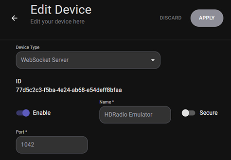
A WebSocket Server accepts WebSocket connections from clients and supports real‑time messaging.
The following configuration fields are displayed when WebSocket Server is selected as the Device Type:
Secure toggle - Enables TLS encryption.
On: Uses encryption (wss://)
Off: No encryption (ws://)
Port - Port on which the server accepts WebSocket connections.
This Device Type is used to uploads a file to an FTP server.
The following configuration fields are displayed when FTP Upload is selected as the Device Type:
Use Passive toggle - Enables passive FTP mode (recommended for firewalled networks).
Host - FTP server address.
Port - FTP server port (default: 21).
Username/Password - Credentials for authentication.
Local File - The path to the file being uploaded.
Remote Directory - The destination folder on the FTP server.
Retry - The number of retry attempts if the upload fails.
This Device Type is used to download a file from an FTP server.
The following configuration fields are displayed when FTP Download is selected as the Device Type:
Use Passive toggle - Enables passive FTP mode.
Host - FTP server address.
Port - FTP port.
Username/Password - Authentication credentials.
Local File - Where the downloaded file will be saved.
Remote Directory - The folder on the FTP server containing the file.
Retry - The number of retry attempts.
A Loopback device sends data back to itself. It is primarily used for testing, debugging, or validating message formatting without involving external systems.
The Search field in the New/Edit Connect Group panel is used to search for specific devices in the group. This search field functions as a dynamic, real‑time search tool. As the user types, the system instantly filters and updates the list.
The Device list in each Connect Group lists the following information about each device.
Device Name - This is the Name of the Device configured when the device was added.
Device Type - This is the Device Type selected when the device was added.
Actions - The Actions column provides quick options to manage Connect Groups:
Edit – Opens the Edit Device panel for editing the device configuration.
Delete – Removes the selected device from the Connect Group.
To edit an existing connect group click the Edit button in the Actions column of a connect group listed in the Connect Groups and Devices list. The Edit Connect Group panel has the same features as the Create New Connect Group panel.
Create a Connect Group and add Devices
Edit a Connect Group and its Devices
 |
Use the following steps to create Connect Groups and Devices: |
option from the Navigation pane. |
Use the following steps to Edit a Connect Group and its Devices: |
option from the Navigation pane. button in the Actions column for the device to remove it from the group. |
Use the following steps to Delete a Connect Group: |
option from the Navigation pane. button in the Actions column. This Prompts for confirmation before removing the Connect Group.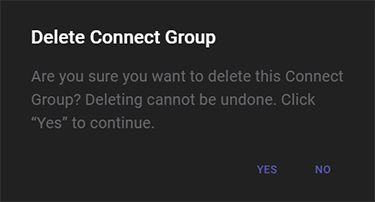
© Copyright 2022 - 2026 AudioDisplay. All Rights Reserved.